
The Machine Home position is fully X+ (carriage right), Y+ (gantry to rear) and Z+ (spindle up).
Often the control will need to make a small adjustment to one side of the Y axis,
to square the gantry to the machine frame. If the adjustment is more than
a few thousandths of an inch, then the control will display a message on
the screen and wait for you to press Cycle Start again, before it makes
the squaring correction move.

If the amount of movement is less than 0.200", then go ahead and press Cycle Start to complete squaring.
If the proposed movement is excessive, then press Cycle Cancel and and
investigate possible interference with gantry homing.
See Y Axis Pairing, Homing and Squaring below.
|
The control starts up in Incremental jog mode. In order to jog the axes in continuous movement, you need to press the INCR/CONT key to switch from incremental to continuous jog mode. |

You can manually change the tool in the spindle using the tool-release button on the right side gantry leg, or using the Macro1 key on the wireless pendant.
To remove a tool:
To load a tool:
The machine has low-pressure external coolant, and high-pressure through-tool coolant. Both can be run in either manual or automatic (programmed) mode.
|
Switch between Auto and Manual coolant control |
| M7 | Through-Tool Coolant On, in Auto mode |
| M8 | Flood (external) Coolant On, in Auto mode |
| M9 | Coolant Off, in Auto mode |
 |
Flood (external) Coolant On/Off, in Manual mode |
 |
Through-Tool Coolant On/Off, in Manual mode |

In addition to the console jog panel, the machine is equipped with a Centroid WMPG-6 wireless MPG handwheel pendant. The handwheel pendant can be used for axis jogging and for cycle start, feed hold, and drawbar control.
To use the MPG pendant, first press its silver power button. The display on the pendant should show a copy of the DRO axis position display.
To move an axis using the handwheel:
NOTE: If you are working with the touch probe or tool setter, and the probe or tool setter is in a tripped condition (LED is lit), then the MPG handwheel will only work on the x1 increment. Select x1 and move Z+ until the probe clears. Then you can select whatever other increment you want.
The handwheel can also be used as a spindle speed override control, or as a feedrate override control.
To adjust spindle speed, turn the increment-select knob to SPIN, then turn the wheel CW to increase spindle speed, or CCW to decrease spindle speed.
To adjust feedrate, turn the increment-select knob to FEED, then turn the wheel CW to increase the feedrate override, or CCW to decrease the feedrate override.
NOTE: if you use the WMPG handwheel to change the feedrate override setting, this takes precedence over the position of the knob on the console jog panel. However, as soon as you turn the knob on the console jog panel again, then its setting will take over. This could cause an abrupt change in axis speed, especially if you had used the WMPG wheel to turn the feedrate override down.
In addition to the MPG handwheel, the WMPG pendant has Cycle Start, Feed Hold, and Tool Check keys. These keys function the same as the equivalent keys on the main jog panel.
There are two axis jog keys: "JOG -" and "JOG +". These keys will jog whichever axis is selected with the axis-select switch, in the jog mode (FAST/SLOW) that is selected on the main jog pendant.
There are four customizable Macro keys. As of January 2024, these keys have the following functions:
 |
Tool Release (unclamp drawbar) |  |
no function |  |
no function |  |
Move to tool-measuring position (front right) |
The WMPG pendant relies on a USB-connected wireless transceiver. This transceiver antenna sits on top of the console, and should be plugged into a USB port on the PC inside the console.
The WMPG pendant requires two AA batteries. The battery compartment
is on the back, underneath the protective rubber cover.
Y Axis Pairing, Homing and Squaring
The machine's moving gantry is the Y axis. It is driven by two separate servo motors, turning ballscrews (leadscrews) on opposite sides of the machine.
The servo motor on the right side (nearer to the control console and cabinet) is the "master" axis, and is called "Y". The Y leadscrew moves the right-side gantry leg forward and back.
The servo motor on the left side (away from the console and cabinet) is the "slave" axis, and is called "V". The V leadscrew moves the left-side gantry leg forward and back.
In normal operation, the two are paired together by the control software. The V axis is made to do everything that the Y axis does, and the two gantry legs move in sync.
During power-up homing, however, it may be necessary to uncouple the paired axes briefly, to square the gantry to the machine base. Because there is a small amount of flex and free-play in the gantry frame, it is possible for one side to be pushed out of alignment with the other side while the machine is powered off.
Homing and squaring of the gantry is done using two home sensors, one on each
side of the machine. The sensor on the right (Y) side is wired to INP4 on the
PLC, and serves as both the Y+ limit switch, and also the Y axis homing switch.
The sensor on the left (V) side is wired to INP8 on the PLC, and is used only
as a homing reference switch. The trip block for the left-side sensor is
approximately three inches forward (Y-) of the trip block for the right-side
sensor, so it trips first as the gantry moves toward the rear of the machine,
and remains tripped all the way to the Y+ home and limit.

The automatic homing sequence begins by moving the paired axes together in the Y+ direction,
to locate the Y+ home and limit switch (the right-side sensor), and then to
back off of the sensor (in the Y- direction) until the encoder index pulse
on the Y axis servo motor comes around. This ensures a highly repeatable
homed position.

Next, the paired axes are moved together, back in the Y- direction, until
the edge of the V home switch (the left-side sensor) is located.

If the gantry is square to the machine, then the distance of the Y axis
(the master servo) away from its home position will be equal to a known
value, which is in the neighborhood of 2.6". This distance is slightly
less than the distance between the Y and V trip blocks, because the Y
home position was backed away from the trip block as far as the first Y
servo index pulse.
The homing procedure checks this distance, and if it is within
an acceptable tolerance, then homing is complete.
If the gantry is skewed in a CW direction (the right side gantry leg is
closer to the front of the machine, and the left side gantry leg is closer
to the back of the machine) then the Y axis will have moved farther than
the expected distance, by the time the edge of the V home switch is found.

In this case, the control will uncouple the paired axes; move the
Y (master) axis by itself a short distance in the plus direction; then
re-couple the paired axes.
If the gantry is skewed in a CCW direction instead, then the Y axis will
have moved less than the expected distance from its home when the V home
switch is found.

In this case, the control will uncouple the paired axes; move the
Y (master) axis by itself a short distance in the minus direction; then
re-couple the paired axes.
In either case, if a correction move was required to square up the gantry, then the control will repeat the initial sequence: homing the paired axes to the Y home/limit switch (right-side sensor) and then backing off to the Y servo motor's index pulse.
If, after automatic homing and squaring, the gantry is not actually square to the machine bed, then there has probably been a mechanical change to the Y axis servo drive train, or to one of the homing blocks or sensors.
In this case, you will need to adjust the squaring distance that is used by the automatic homing and squaring sequence.
The machine instructions for homing all of the axes are in the CNC macro file cncm.hom, located in the c:\cncm directory.
The expected Y axis position (distance from home) at the edge of the V home sensor, when the gantry is square, is set in a variable assignment at the top of the cncm.hom file. For example:
#101 = -2.575 ; Expected Y axis machine position when slave home sensor tripsThis squaring value set in variable #101 will always be a negative number.
If anything causes the trip location of either sensor to change; or if the relationship between Y axis servo motor rotation and Y axis ballscrew rotation changes; then the expected distance in the cncm.hom file will need to be recalculated. Such conditions would include:
If it is necessary to check or recalculate the square distance, use this procedure:


The amount by which you need to change the squaring value in cncm.hom will be larger than the amount of Y axis error that you measure between the two pins.
That is because the squaring correction is applied between the Y and V leadscews, which are approximately 135.5 inches apart; while the pins will necessarily be closer than that.
If the X distance between the test pins is dx, and the difference in their apparent Y positions is dy, then the amount by which you need to increase or decrease the squaring value is:
adjustment = 135.5 * dy / dx

In normal operation, the Auxiliary keys on the jog panel have the following functions:
 |
No function |  |
No function |  |
No function |
 |
Move to tool-measuring position (front right) |  |
Show V axis (slave) servo load on Y axis load meter |  |
No function |
 |
No function |  |
No function |  |
No function |
| (Aux10) | No function | (Aux11) | No function | (Aux12) | No function |
| (Aux13) | No function | (Aux14) | No Function |
Aux keys with no default function shown above are available for
custom PLC-controlled features, or for features assigned through
Machine Parameters 188-199. See the Configuration chapter of the M-Series Operator's Manual.
M Function Summary
| M0 | Stop (wait for Cycle Start) |
| M1 | Optional Stop (wait for Cycle Start) |
| M2 | Program Restart (with wait for Cycle Start) |
| M3 | Spindle Start CW / Forward |
| M4 | Spindle Start CCW / Reverse |
| M5 | Spindle Stop |
| M6 | Change Tools |
| M7 | Through-Tool Coolant On |
| M8 | External Flood Coolant On |
| M9 | Coolant Off |
| M89 | Move to tool-measuring position (front right, G30 P3) |
See the M-functions chapter of the Centroid M-Series Operator's Manual for descriptions of standard M functions.
M functions M91 and above are used internally in custom macro programs, but
are generally not used directly in user machining programs.
Machine Parameters Summary
The following parameters on the Centroid Machine Parameters table are used for features specific to this machine, or have settings specific to this machine.
| Parameter | Meaning | Value | Notes |
|---|---|---|---|
| P35 | Spindle axis | 6 | Use axis #6 for spindle settings |
| P57 | Load meters | 47 | Show PLC-controlled load meters for all axes and the spindle |
| P64 | Axis pairing | 2 | Slave axis #4 (V) to axis #2 (Y) |
| P143 | DRO display | 11 | Show load meters on DRO, plus distance-to-go display |
| P146 | Feedrate threshold | 3 | Activate Feed Hold if Feedrate Override is turned down below 3% |
| P178 | Output options | 4 | Use bipolar analog spindle speed/direction signal |
| P710 | Spindle drive unit start-up time | 10000 | Time (ms) after closing safety relay, before we expect the spindle drive to be ready. |
| P773 | Analog zero | 32752 | Analog output value for zero RPM (midpoint of range) |
| P990 | Spindle load meter scale (Volts) | 10.0 | Analog volts from Siemens spindle drive, for full-scale spindle load |
| P991 - P994 | Servo load meters scale (Volts) | -2.5 | Analog volts from Yaskawa servo drives, for full-scale motor load |
For all other Machine Parameter functions, see the Configuration chapter of the
Centroid M-Series Operator's Manual.
Errors and Faults
The PLC program can generate various fault and error messages, in addition to those listed in the Centroid operator's manual.
You can use the PLC Diagnostic display on the computer to view some of the Centroid PLC input, output, and memory locations mentioned with the error and fault conditions below. At the control's main screen, press Alt-I to activate the PLC Diagnostic display. Press Alt-I again to dismiss it.
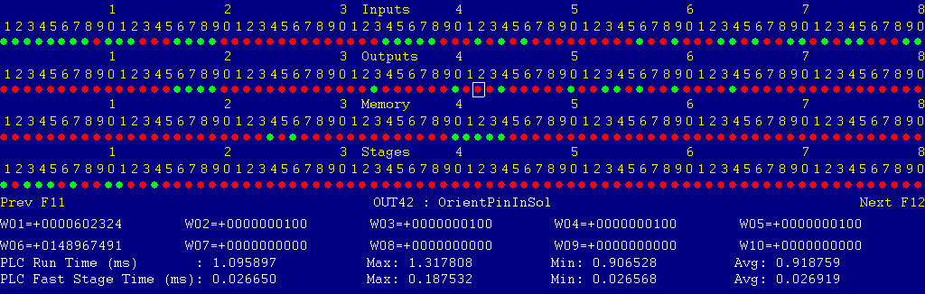
The Diagnostic display shows four rows of red and green dots: the first row shows PLC inputs 1 through 80; the second row PLC outputs 1 through 80; the third row PLC memory bits 1 through 80; and the fourth row PLC program stages 1 through 80.
You can use the arrow keys to move a highlight box over any of these locations. The name of the highlighted location will be displayed at the bottom center.
Below the four rows of bit status information are ten numeric ("word") variable values, labeled W1 through W10. Some of these variables also hold useful status information, described with the fault and error conditions which follow.
There are multiple pages of PLC Diagnostic information. You can page sideways using the F12 and F11 keys. For example, pressing F12 once will scroll to the page showing INP81 - INP160, W11-W20, etc..
Pressing F12 nine times in total will scroll to the page showing INP721 - INP800, which includes the probe and tool detector inputs (INP769 - INP772).
Most fault conditions must be cleared by pressing and releasing the Emergency Stop button.
The control detected an internal error in processing the PLC logic program.
Report this error to your dealer, along with the values from W14 and W15. Also report what function the machine was performing when the fault occurred.
You must shut down and cycle the power to clear this fault.
References:
PLC W14: Copy of internal SV_PLC_FAULT_STATUS, indicating the type of problem
PLC W15: Copy of internal SV_PLC_FAULT_ADDRESS, indicating the location of the problem
There was an on-board communication error on the Oak control unit.
Contact your dealer.
There was an on-board communication error on the Oak control unit.
Contact your dealer.
One or more of the Yaskawa servo drives is reporting a fault condition.
Check the LED displays on the axis drives themselves for an alarm code.
See Chapter 10 of the Yaskawa Sigma V User's Manual for information about specific alarm codes.
Press and release Emergency Stop to clear the fault.
References:
PLC MEM16: Axis #1 (X) drive status.  Green = okay, Red = fault
PLC MEM17: Axis #2 (Y) drive status.  Green = okay, Red = fault
PLC MEM18: Axis #3 (Z) drive status.  Green = okay, Red = fault
PLC MEM19: Axis #4 (V) drive status.  Green = okay, Red = fault
Schematic: Lines 32, 36, 40, 44
The spindle drive unit or its power module is reporting a fault condition.
Check the LED indicators on the spindle drive and power module themselves for a fault code.
Press and release Emergency Stop to clear the fault.
References:
PLC INP10: Spindle drive status.  Green = okay, Red = fault
Schematic: Lines 15, 21, 126
The control unit detected loss of communication from the operator panel in the Console.
Check for damage or disturbance to the cable between the console and the Oak control unit in the control cabinet.
Press and release Emergency Stop to clear the fault.
References:
Schematic: Lines 89, 107
The operator panel reported back to the control unit a loss of communication from the control unit. This indicates the return signal from the pendant is functioning normally, but the outgoing signal may have problems.
Check for damage or disturbance to the cable between the console and the Oak control unit in the control cabinet.
Press and release Emergency Stop to clear the fault.
References:
Schematic: Lines 89, 107
You attempted to start the spindle, but a touch probe is plugged into the probe receptacle.
Remove the probe from the spindle, and unplug it from the probe receptacle. Then try the spindle operation again.
References:
PLC INP771: Probe detect input.  Green = probe connected, Red = probe not connected
Schematic: Lines 97, 105
You exited the CNCM control software without first pressing Emergency Stop.
Press and release Emergency Stop to clear the fault.

The 24VDC supply from switching power supply PS2, which provides current for all of the PLC inputs as well as logic power for the servo amplifiers, has gone out. This likely indicates that a +24V wire is shorted to chassis ground somewhere. +24V wires from PS2 are all labeled "24VDC1".
If the 24V supply is shorted to chassis ground, the green LED on supply PS2 will probably be blinking on and off.
Disconnect loads, such as the circuits to the bridge master junction box, bridge slave junction box, spindle junction box and high-pressure coolant unit, to isolate the source of the problem.
References:
PLC INP32: indicates PS2 status: Green = 1 = good; Red = 0 = off
Schematic:  Lines 61, 63, 131, 135, 136, 140

The spindle motor fan has tripped the overload (FR305S) on its starter (KM031).
Investigate possible causes for the overloaded motor.
Allow time for the overload unit to cool, press the reset button on the overload unit, then press and release Emergency Stop to clear the fault.
References:
PLC INP19:  indicates FR305S state: Red = 0 = okay; Green = 1 = tripped
Schematic:  Lines 11, 134
The low-pressure flood coolant pump has tripped the overload (FR317H) on its starter (KM043).
Investigate possible causes for the overloaded motor.
Allow time for the overload unit to cool, then press the reset button on the overload unit, press and release Emergency Stop to clear the fault.
References:
PLC INP20:  indicates FR317H state: Red = 0 = okay; Green = 1 = tripped
Schematic:  Lines 9, 134
The JetCool high-pressure coolant unit is reporting a fault.
Check indicators on the JetCool panel for possible causes. Press the Alarm Reset button on the CoolJet unit, then press and release Emergency Stop to clear the fault.
References:
PLC INP21:  indicates CoolJet status: Green = 1 = okay; Red = 0 = fault
Schematic:  Lines 26, 135
The PLCADD1616 expansion board has failed to communicate properly with the Oak board.
Check the gray PLC expansion cable that connects the PLCADD1616 board to the header at the bottom of the Oak board. Check for green 5V power and "PLC OK" LED indicators on the PLCADD1616 board.
On this machine, there should be one I/O expansion boards connected, and Machine Parameter 900 should be set to 1.0.
References:
PLC W36: bitmap of detected PLC expansion boards.  1 = one board detected
Machine Parameter 900: bitmap of expected PLC expansion boards.  1 = one board expected
The Emergency Stop button on the bridge master junction box (on the right-side gantry leg) is pressed.
Twist and pull the emergency stop button to release it.
A false alarm of this type may be due to a failure of relay KR032. The emergency stop button controls the relay coil, and relay contacts signal the PLC.
References:
PLC INP12:  Indicates Emergency Stop button status: Green = 1 = okay; Red = 0 = pressed
Schematic:  Lines 67, 127
The Emergency Stop button on the bridge slave junction box (on the left-side gantry leg) is pressed.
Twist and pull the emergency stop button to release it.
A false alarm of this type may be due to a failure of relay KR033. The emergency stop button controls the relay coil, and relay contacts signal the PLC.
References:
PLC INP13:  Indicates Emergency Stop button status: Green = 1 = okay; Red = 0 = pressed
Schematic:  Lines 68, 128
You attempted to start the spindle with the spindle drawbar unclamped (open). Close the drawbar, then try the operation again.
References:
PLC INP23:  Indicates air pressure to release drawbar (SP042): Green = 1 = pressure; Red = 0 = no pressure
PLC OUT24:  Tool unclamp solenoid (YV4): Green = unclamp tool; Red = idle
Schematic:  Lines 136, 176
The PLC detected an unexpected closed circuit on a vacant input. This may indicate an electrical noise or interference issue.
Report the message to your dealer.
References:
PLC INP17: An unused input.  Green = 1 = circuit closed, Red = 0 = circuit open
Schematic: Line 133
The PLC program requested display of a message on the screen, but the provided message code was not valid.
This indicates an error in the PLC program. Report the message to your dealer, along with the value in PLC variable W16.
References:
PLC W16: stores the invalid message code
The PLC hardware detected the presence of an I/O expansion board, but the setting of Machine Parameter 900 did not tell it to expect that board in the system.
On this machine, there should be one I/O expansion board installed, and Machine Parameter 900 should be set to 1.0.
References:
PLC W36: bitmap of detected PLC expansion boards.  1 = one board detected
Machine Parameter 900: bitmap of expected PLC expansion boards.  1 = one board expected
A previous PLC fiber communication fault (9022 or 9023) has been fixed and cleared.
You pressed a keyboard shortcut key for jogging the machine or starting a cycle, but those shortcuts have been disabled on this control.
A previous fault condition has been cleared by pressing Emergency Stop.
Wiring Schematics
Schematic Page 1 - Power and drives, logic supplies
Schematic Page 2 - Safety relay, M400 console, Oak unit, PLC inputs
Schematic Page 3 - PLC outputs
27-Sep-2024
![]()

